ubit-rc.de - 6040Z CNC Router
Controlling the E100 Inverter (vfd) with ModBus
The supplied inverter Nowforever E100 can be controlled with ModBus. ModBus is a simple communication protocol which can control e.g. with a simple RS485 interface - multiple devices. One device acts as a master - all other (up to 31 devices) as slaves.
As i use an old pc with windows XP for the router that has a RS232 interface i ordered a RS232/RS485-converter with screw sockets for less than 10 €. I then connected the converter with the sockets on the inverter (found under a lid).
converter + with +485 on inverter
converter - with -485 on inverter.
I used a simple cable i had laying around. In theory you should use shielded twisted pair cables - shielding connected to GND - but it seems to work with simple cables too.
After this i installed QModBus to test the connetion. You can get QModBus here: http://qmodbus.sourceforge.net/
Before the test you should check if the settings of the inverter for serial communication are correct. With the enter key of the inverter keypad you get to the settings. The following settings are important:
- P0-055
This is the ModBus slave address. I set it to 1. - P0-056
This is the communication speed. 0=2400 bps, 1=4800 bps, 2=9600 bps, 3=19200 bps, 4=38400 bps. I set it to 4 to have the fastes communication possible. - P0-057
Here you set additional communication parameters. I set it to 0. That means: 8 Bit, no parity checking, 1 stop bit
To configure the inverter you start with selecting the register group - here P0. After this you can select the register number with the up and down arrow keys. Tipp Enter again and you can set the value. With ESC you go back.
If you start QModBus you have to configure the serial communication:
- Serial port: Depends on your pc and converter. For me it was COM1
- Baud: The bps set in the inverter. For me: 38400 bps
- Data bits: 8
- Stop bits: 1
- Parity: none
- Slave ID: 1
- Function code: Read Holding Registers (0x03)
- Start address: 1280
- Num of coils: 8
With these settings you tell QModBus to read the ModBus-Registers 1280 to 1287 (in hex this is 500H to 507H) from the given slave device. According to the inverter manual those registers are used for the following (i listed only the most important settings).
| Register (hex) | Meaning |
| 500H | Bit 0 = 0: Spindle does not turn Bit 0 = 1: Spindle is turning Bit 1 = 0 : Spindle turns CW Bit 1 = 1: Spindle turns CCW |
| 501H | Frequency setting |
| 502H | Output frequency |
| 503H | Output current (multiplied by 10) |
| 504H | Output voltage (multiplied by 10) |
| 507H | Internal temperature of the inverter |
Register number are given in hex notation in the inverter instruction manual. This is a number system where every digit can take a value of 0-15. The letters a-f are used to represent digit values 10-15. You can recognise hex values mostly by seeing a letter "H" appended or the term "0x" prepended to the value. There are hundreds of converters in the web to convert hex values to decimal numbers used e.g. by Mach3. This is why register 500H of the inverter has to be set as register 1280 (decimal) in Mach3.
To control the inverter you have to use some additional registers to write to. Here a short listing:
| Register (hex) | Meaning |
| 900H | Bit 0 = 0: Spindle off Bit 0 = 1: Spindle on Bit 1 = 0: CW Bit 1 = 1: CCW |
| 901H | Frequency control |
When you click on "Send" the registers are read from the inverter. The result should be visible in the bus monitor. If you change the frequency with the potentiometer on the inverter and start/stop the spindle with the inverter keypad, click on send again, you should see changes. If this does not work you maybe have selected the wrong serial port or the connection wires have to be switched. You have to check until this works to be sure that you can connect from Mach3 too. There are reports in the web that some people have to connect GND from PC/converter and inverter to make the communication work. For me the 2 wires worked.
To control the inverter you can use the so called brains in Mach3. These are simple logic ladders that you can build with the brain editor. For this description i assume that you are using the default screenset 1024.set.
First we have to activate ModBus communication in Mach3. To do this select "Config"-"Ports & Pins" from the menu and enable "ModBus Input Output Support" and "ModBus PlugIn Supported":
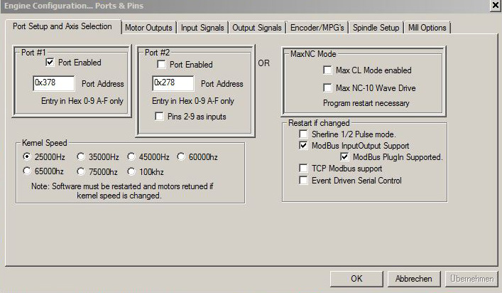
You have to end and restart Mach3 to make this settings effective.
Now we have to tell Mach3 which ModBus registers to use. That is done in "Function Cfg's"-"Setup Serial ModBus Control" menu:
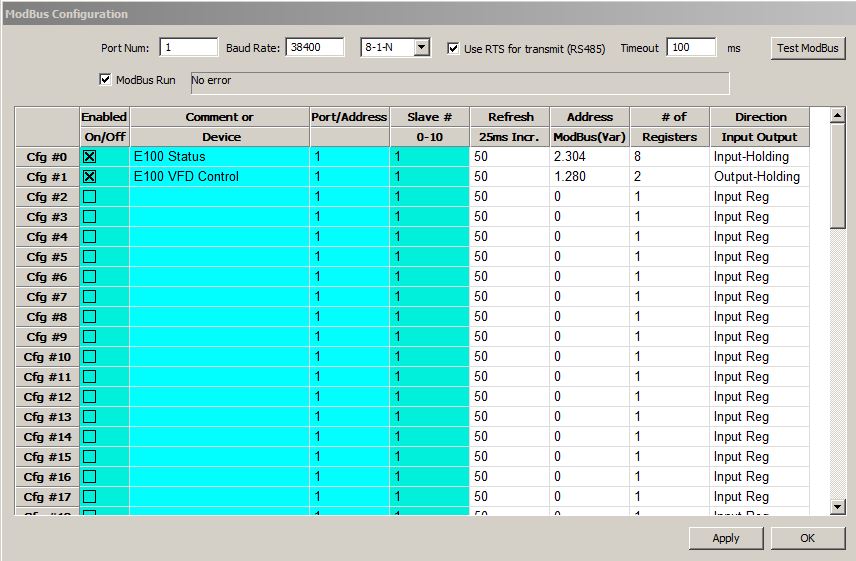
Sorry - the screenshot is WRONG. 2304 and 1280 are swapped.
With this settings we create two register groups that we can access later. The first group CFG#0 is used to read data from the inverter, starting with register 1280 (=500H). The second group (from register 900H = 2340 decimal) is used to send commands to the inverter - to control the spindle. Very important is the checkbox "ModBus Run"! If this is not checked it will not work! It is a good idea to finish Mach3 and start again.
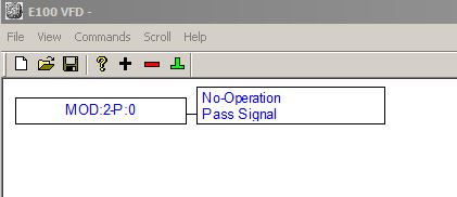
Now we can start building the brain. In Mach3 use menu "Operator"-"Brain Editor" to start the brain editor. We use "E100 VFD" as the name of the new brain.
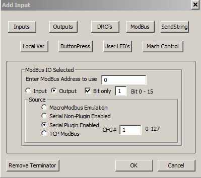
With the brain editor we can create so called "lobes". Let's start with the output frequency of the inverter that we want to transfer to Mach3. To do this we start adding a knot (Menu "Commands"-"Add" or use the plus icon). We click on "ModBus" and set the following values:
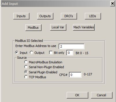
CFG# is 0 - this is the first register group defined above starting with 500H. In the field "Enter ModBus Adress to use" we insert a 2. Thus Register 500H+2 = 502H is accessed. According to the register table this register contains the output frequency of the inverter. Click on "OK" and we get the following result:
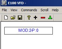
Now we click on the new box (it gets green) and click again on the plus sign. This time we choose "No Operation" and click "OK":
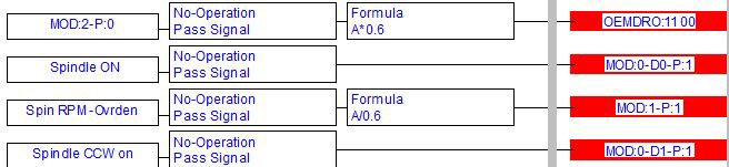
The inverter sends the frequency with 2 decimal places as an integer. If the frequency is 200 Hz, the ModBus register shows a value of 20000. We want to know the rpm of the spindle. To get it we have to add a formula and multiply the value by 0.6. 20000 * 0.6 = 12000. We click on the No-Operation Box (gets green) and again on Add (plus icon). In the dialog we click on "Formula" and insert "A*0.6":
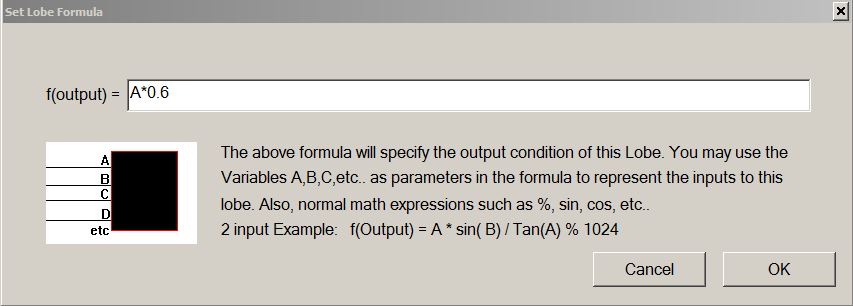
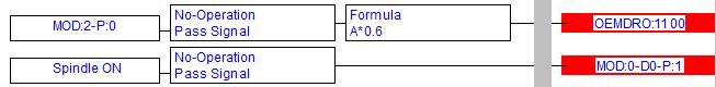
We get the following result:
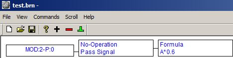
To be able to show the value later we have to end the lobe. We mark the box with the formula and click on the green terminator symbol (or menu "Commands"-"Terminate Lobe"). In the dialog we choose "DRO's" and set the DRO number to 1100:
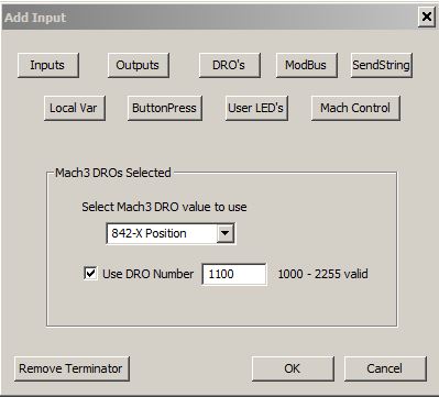
The result should look like this:

Now we save the new brain into the subdirectory "Brains" of our Mach3 installation directory with the name "E100 VFD.brn" and change to Mach3. There we choose "Operator"-"Brain Control" from the menu. In the dialog wie reload all brains by clicking on "Reload all Brains". Our new brain should show up in the list. We click on it and set the checkmark on "Enabled" (IMPORTANT!). Now we click on "View Brain". The Brain-Monitor opens - looks nearly identical to the brain editor but shows the current values of the components.

If we now start the spindle with the keyboard of the inverter/controller and change the frequency we should see the current output frequency and spindle speed in the brain monitor. If this works we can go on to the actual spindle control.
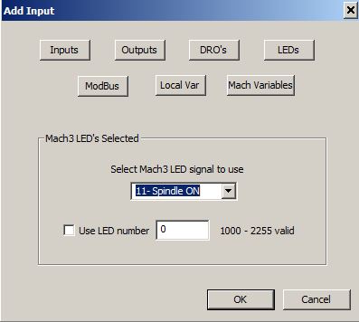
We open the brain editor again, and make sure that no box is green and generate a new lobe with the plus button. This time we use an LED that is controlled by Mach3. LED 11 named "Spindle On" should work.
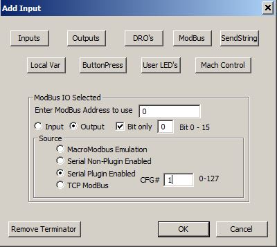
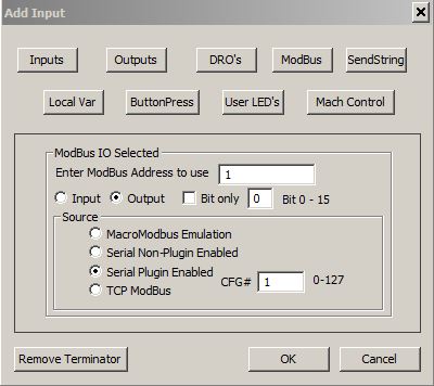
Again we add a "No Operation". As Terminator we have to use ModBus:
We get:
Now we save the brain and change to Mach3. Menu "Operator"-"Brain Control". There we reload the brain (or simply "Reload All Brains") and start the brain viewer with our brain. If we start the spindle with Mach3 (e.g. by typing the G-Code M3 in the MDI screen or by clicking on the spindle controls) we should see that the new lobe changes to green in the brain viewer. But our spindle does not turn on automatically. To do this we have to set the inverter to be controlled by ModBus and not by the local keypad.
We have to change setting P0-000 to a value of 2. After we did this we should be able to start and stop the spindle from Mach3.
Now to the rpm control. To make this work we have to set P0-002 (the main frequency source) on the inverter to 6 (serial communication). Now we start the brain editor again and build a new lobe. We start with DRO "202 - Spin RPM - Overden". This is the current spindle speed including manual override. We add another "No Operation". Now we again need a formula. We have to divide the spindle RMP through 0.6 to get the frequency. Then another ModBus terminator with the following setting:
In total this should look like this:
Back to Mach3, reload brain, start brain viewer and play with the spindle settings in Mach3. We should now be able to turn on and off the spindle and set the rpm.
Now we add the direction of rotation to the controllable parameters. We open our brain in the brain editor and start another new lobe. This time we start with LED "165 - Spindle CCW on". Another "No Operation" and as a terminator we neet Modbus Register 900H, Bit 1 - this is the control bit for CW vs. CCW:
In total:
Now we have full control of our spindle. A nice addition would be to show the current frequency or spindle rpm in Mach3. No problem. In our first lobe we set the spindle frequency into DRO 1100. We just have to change the user interface (the screenset). We use the Mach3 screen designer MachScreen (URL: http://www.kd-dietz.com/klausphp/). We install it and copy the standard screenset "1024.set" in the Mach3 directory to a new file "6040.set". Now we start MachScreen and open this new screenset.
On page 1 we find a description field "RPM" followed by a display field for the spindle speed:
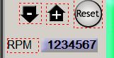
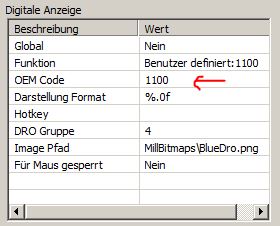
When we click on the display field with the mouse a popup opens where we can choose an element (multiple elements are in different layers so we have to choose which one we want). The choosen element is marked and we can see what Mach3 displayes here in the property window. We change this to OEM code 1100:
On page 2 we find the same element again. We change this too.
Now we save the screen set in MachScreen and load it in Mach3. The RPM field should now show the current spindle rpm.
We optionally could add the output current or inverter temperatur e.g. to the diag screen of Mach3. You should be able find out how this works by yourself now.